Understanding the Blueprint of a House: A Guide to Reading Technical Construction Plans
Demystify the technical drawings of your future home. Learn to read house blueprints, interpret symbols, and choose the right construction set.
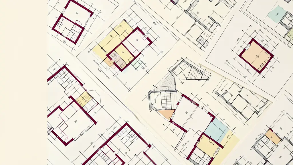
A house blueprint is a comprehensive set of technical construction documents that translate an architectural vision into a buildable reality. While often confused with a simple layout, these scaled drawings provide the precise structural, mechanical, and legal instructions required to obtain municipal permits and execute a safe construction.
No time to read?
- A house blueprint is a full set of technical documents, not just a single floor plan.
- Reading a set requires understanding the scale, the symbol legend, and the relationship between floor plans and elevations.
- Complete sets include site plans, foundation layouts, and mechanical schematics necessary for city permits.
- Customization is essential to align stock blueprints with local zoning laws and lot constraints.
What Exactly Is a House Blueprint?
When most people discuss a house plan, they are referring to the aesthetic arrangement of rooms. However, a professional blueprint of a house is far more than a floor plan. It is a rigorous technical manual that serves as the legal and structural foundation for the entire project.
A simple floor plan shows where the kitchen sits in relation to the living room, but the full blueprint set defines how the house stays standing. It includes the depth of the footings, the gauge of the steel rebar, the placement of hurricane straps, and the specific energy efficiency requirements of the local building code. Without these detailed specifications, a contractor cannot accurately bid the project, and a city inspector cannot approve the build.
To navigate these documents, you must first understand house plan symbols. These standardized icons represent everything from the swing of a door to the type of window casing, ensuring that every professional on the job site, from the plumber to the framer, speaks the same visual language.
The Anatomy of a Complete Blueprint Set
A professional set of construction drawings is organized into specific sheets, each serving a distinct purpose. Missing even one of these can lead to costly construction halts or failed city inspections.
- Site Plan: This is the map of the property. It shows the house’s exact location on the lot, property lines, easements, and the positioning of the driveway and curb cuts.
- Foundation Plan: The structural starting point. It details the footings, slab thickness, and any walk-out basement requirements.
- Floor Plans: The horizontal layout of each level, defining room sizes, interior partitions, and the overall traffic flow.
- Exterior Elevations: Vertical views of the front, rear, and sides of the home, illustrating the exterior finish and the roof pitch.
- Section Drawings: These act as « cuts » through the house, revealing internal stacking, vaulted ceilings, or tray ceiling details.
- Electrical and Plumbing Schematics: The nervous system of the home, mapping out outlets, lighting, and the main water and waste lines.
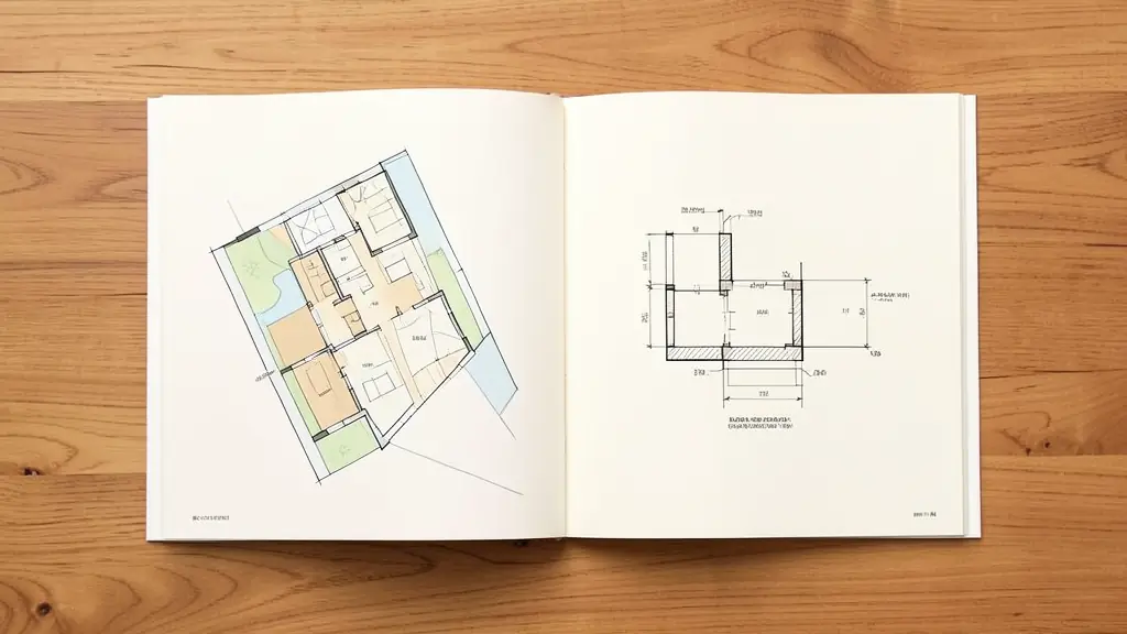
How to Read and Interpret House Plans
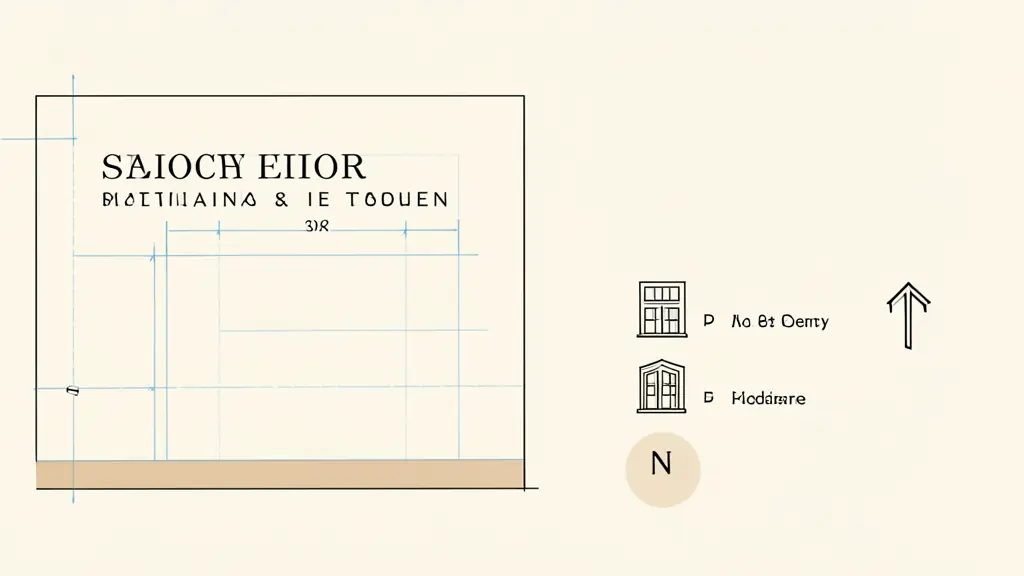
Reading technical plans requires a shift from looking at a picture to analyzing a data set. Every sheet begins with the title block, located in the margin. This area is the « ID card » of the project, containing the project name, the sheet number, the designer’s details, and the revision date. Checking the revision date is critical to ensure you are not building from an obsolete version of the plan.
Understanding Scale and Dimensions
Blueprints are scaled drawings, meaning a small measurement on paper represents a large distance in reality. Common scales include:
* 1/4″ = 1 foot (often written as 1/4″ = 1′-0″)
* 1/8″ scale (used for larger projects or site plans)
Standard paper sizes for these documents typically range from 18″×24″ to 30″×42″. When reading dimensions, look for the legend or symbol key to decode specific markers. For example, door swings are represented by arcs to show the direction of travel, and windows are identified by standard codes such as 3068, 3080, or 4040, which denote the width and height of the unit.
Identifying Wall Types
Not all walls are created equal. When analyzing a floor plan vs elevation, you must distinguish between load-bearing walls, which support the weight of the roof and upper floors, and interior partitions, which simply divide spaces. Load-bearing walls are often thicker or indicated with specific structural symbols to warn contractors against removing them without proper reinforcement.
Floor Plans vs. Elevations: The Critical Difference
The most common mistake for beginners in reading architectural blueprints is attempting to understand a three-dimensional object using only one perspective. You must constantly toggle between the horizontal and vertical views to visualize the final structure.
The floor plan provides a bird’s eye view, focusing on the « footprint » of the home. It is where you analyze the heated and cooled interior space and the movement between rooms. Elevations, conversely, provide the « face » of the house, showing the vertical height, the placement of windows, and the geometry of the roof.
| Feature | Floor Plan (Horizontal) | Elevation (Vertical) |
|---|---|---|
| Perspective | Bird’s eye view | Side-on view |
| Primary Focus | Room layout and traffic flow | Exterior appearance and height |
| Key Details | Door swings, wall thickness, closets | Roof pitch, siding, window heights |
| Purpose | Spatial organization | Aesthetic and height compliance |
From Paper to Property: How Blueprints Drive Construction
Once the design is finalized, the blueprints transition from a creative tool to a legal contract. They serve as the « source of truth » for the entire build. For contractors, these documents eliminate guesswork; if a blueprint specifies a certain grade of lumber or a specific placement for a bump-out, that is exactly what must be installed.
Beyond the job site, these plans are the primary requirement for municipal permit approvals. City officials review the set against local zoning laws to ensure the home doesn’t encroach on setbacks or violate height restrictions. Furthermore, the technical details allow for precise material take-offs. By calculating the exact square footage of the foundation and the linear footage of the walls, builders can provide accurate quotes and avoid the « hidden costs » that often plague unplanned projects.
Choosing and Customizing the Right House Plan
Selecting a stock plan is an efficient starting point, but it is rarely a « plug-and-play » solution. To move from purchase readiness to actual construction, you must filter and adapt the plan to your specific constraints.
When browsing collections of house plans, use filters to narrow your search by:
* Square footage and number of stories.
* Bedroom and bathroom counts.
* Garage capacity and architectural style.
Once a plan is selected, customization is necessary to align the drawings with your lot’s topography. For instance, a plan featuring a walk-out basement is only viable on a sloping lot. Additionally, your architect or builder must review the set for local code compliance, which may include adjusting for wind loads in coastal areas or seismic requirements in active zones. This ensures that the final construction is not only beautiful but legally compliant and structurally sound.
For those unsure of the spatial flow, interactive virtual tours or a detailed walk-through of the plan can help confirm that the layout meets your daily needs before the first piece of concrete is poured.
FAQ
Who typically prepares and reviews a house blueprint set?
Architects and structural engineers prepare the blueprints to ensure safety and design integrity. These sets are then reviewed by city building inspectors for permit approval and by general contractors for execution.
Why are blueprints drawn to scale?
Scale ensures that the proportions of the house are accurate relative to the actual size of the lot. This allows builders to calculate precise measurements for walls, rooms, and site placement without guesswork.
When do revisions to a blueprint become necessary?
Revisions occur during the ‘redlining’ phase when a city inspector identifies a code violation, or when a homeowner requests a layout change. Significant changes often require a permit amendment.
Envie d'aller plus loin ?
Laisse ton email, on te prévient dès qu'un nouvel article sort.